


Aerospace Multi-Axis Marking Station
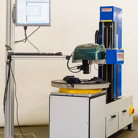
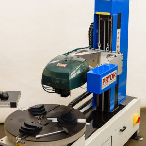
The pioneering Multi-axis Marking Station is a marking and verification machine. This dot-peen marking and machine vision system is designed to mark and verify large, cylindrical components such as aerospace turbine housings.
- Features
- Video
- Technical Data
Features
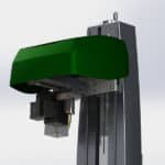
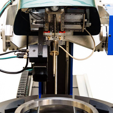
The dot peen marking head has a number of different marking window size options; ranging from 100mm x 100mm to 300mm x 150 mm and custom marking window sizes are also available on request. The marking head has x- and y-axes that move the stylus within the marking window. The marking head is also mounted on a z-axis column that can either be manually adjusted or motorised. The z-axis column positions the marking head at the optimal distance from the component to be marked and for larger components an extended z-axis column is also an option. The state-of-the-art ‘autosense’ feature automatically positions the stylus at the optimal distance from the component at the beginning of each marking operation, ensuring repeatability and consistency of the mark.
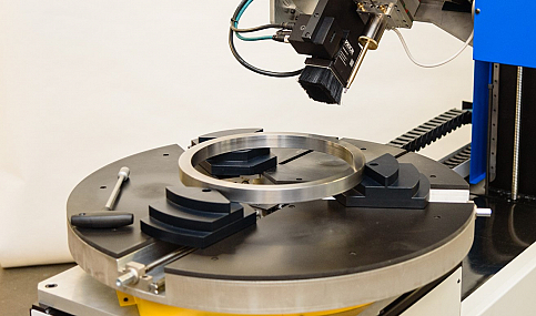
The marking head also houses a machine vision camera with an integrated light source. The z-axis is used to position the camera to the correct height and the x- and y-axes move the camera to the correct position relative to the component. The camera is provided with a shroud to control the lighting conditions and minimise the effects of any variations in ambient lighting. This machine vision has the ability to verify the quality of the marked codes against international marking standards, including: AS9132, JES131, AIM-DPM-Guideline, MIL-STD-130, ISO15434 and ISO16022. It also allows the operator to read and capture data from the marked component; critical for data-driven manufacturing and process control, allowing measurability and eliminating quality defects. The machine vision camera also enables the pioneering automated component alignment capability. This determines the correct position of the mark on the component, automatically rotating the component to the correct location using a “learnt” reference feature.
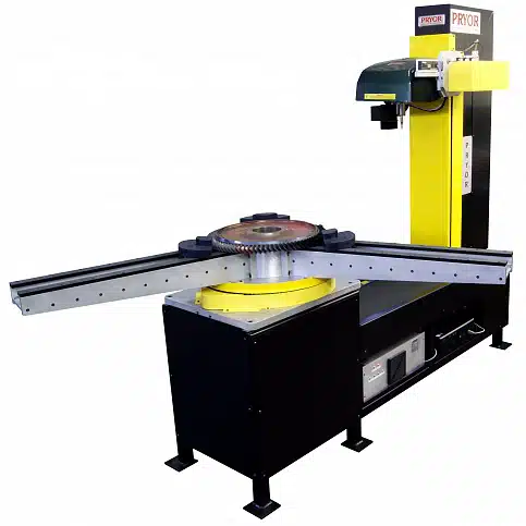
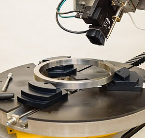
The component is rotated on a motor driven rotating table which forms the basis of the fixture and allows controlled rotation of heavy parts. The rotating table is available in various dimensions to fit the part being marked. The marking head is mounted on a programmable motorised horizontal axis which alters the proximity of the part to the marking head. It also allows for very large parts to be marked by the machine.
The marking head can also be fitted with a motorised tilt facility to allow for unusually-shaped components.
Video
Technical Data
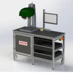
- Machine Dimensions:
Total Height: 1900mm
Width: 1000mm (with doors closed, 1500mm with controller door opening) plus separate HMI pedestal
Depth: 2200mm
- Power supply: a standard 230 / 110 Volt, single phase, 10 amp 50 / 60 Hz power supply (no pneumatics are required) although the internal power connections will have IEC plugs. The power supply must be free from electrical interference such as voltage spikes.
- The equipment will be provided with its own isolation switch and emergency stop button.
- The equipment is suitable for operating in a normal workshop environment without excessive levels of dust in the atmosphere and with no direct impingement of abrasives or liquids.
- The noise levels generated by this marking process are typically in the range 75-80dBA (LEQ). The component shape/size/material etc. have a great influence upon the noise levels produced.
Similar products to consider
-
 This product has multiple variants. The options may be chosen on the product pageQuick View