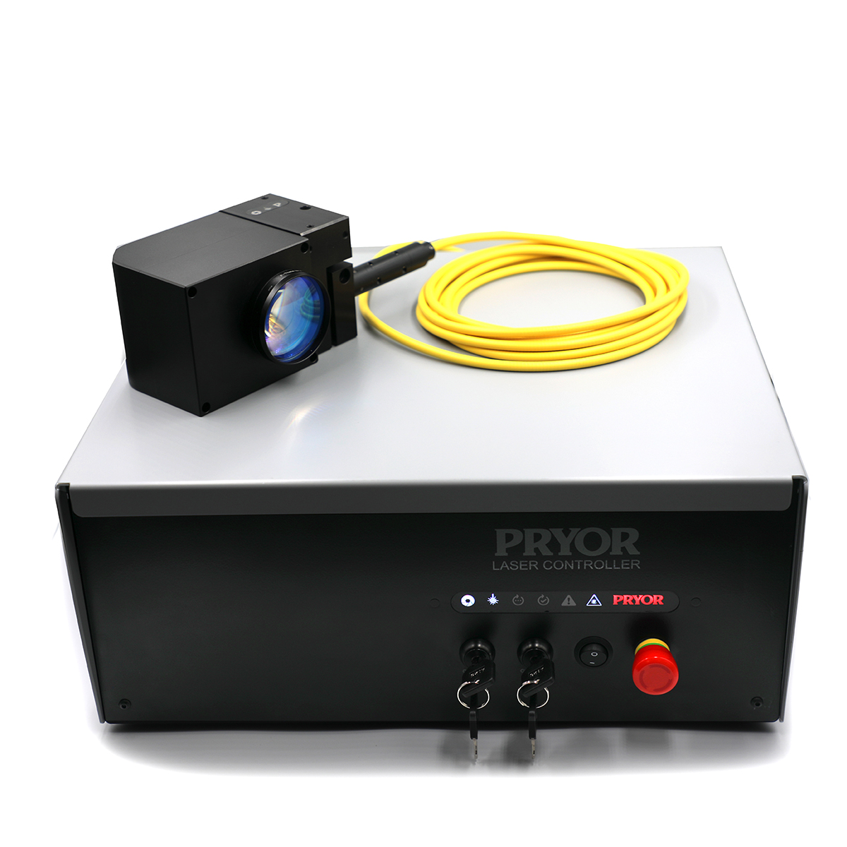
Integrator Laser System
The Pryor Integrator Laser is our new MOPA fibre laser built for system integrators and OEM manufacturers. The updated system now uses the latest MOPA (Master Oscillator Power Amplifier) source technology, a significant step forward that delivers greater control, superior marking on demanding materials including aluminium and engineering plastics, and consistently better contrast across the full power range.
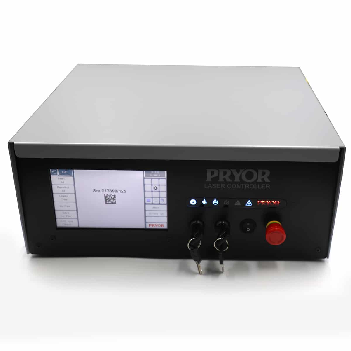
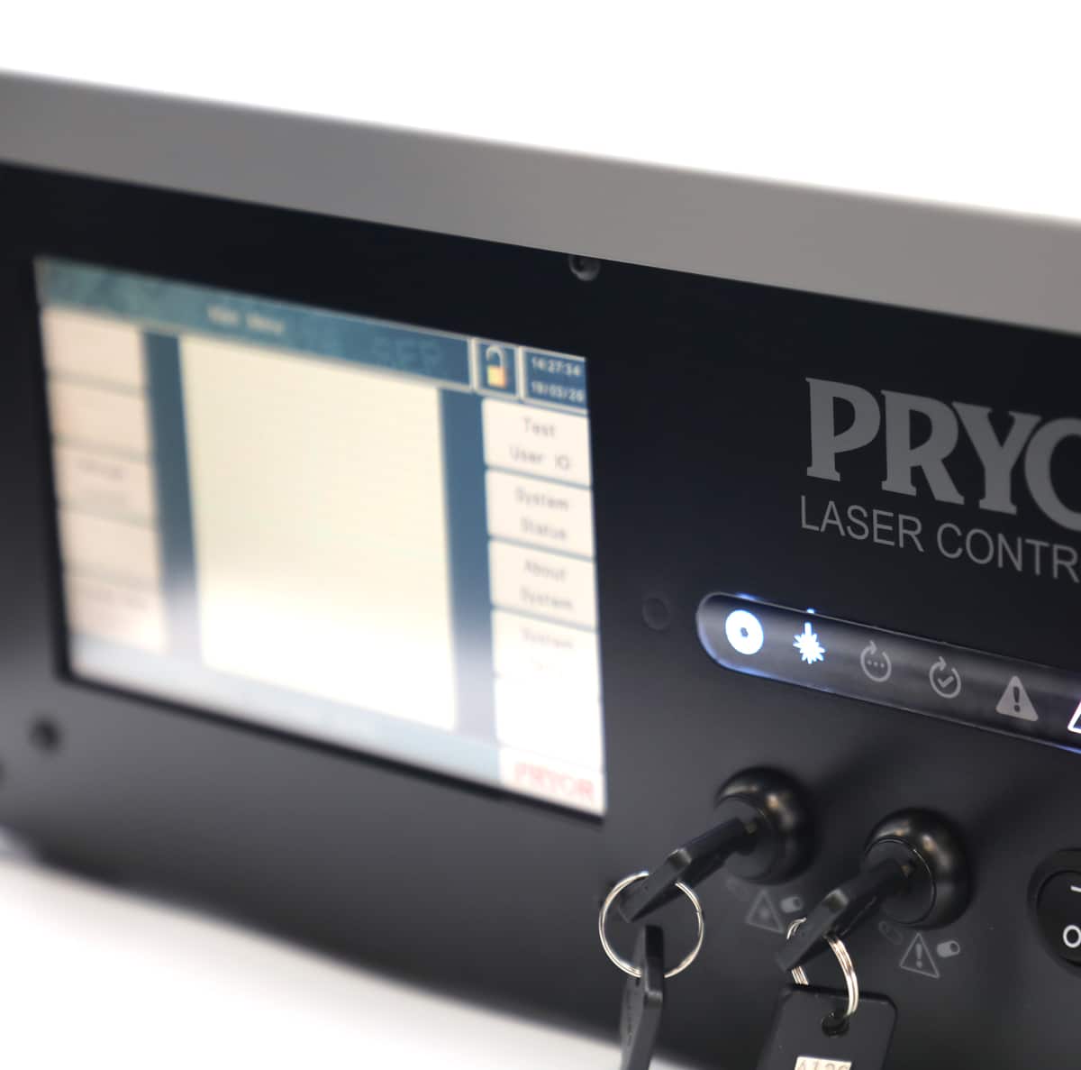
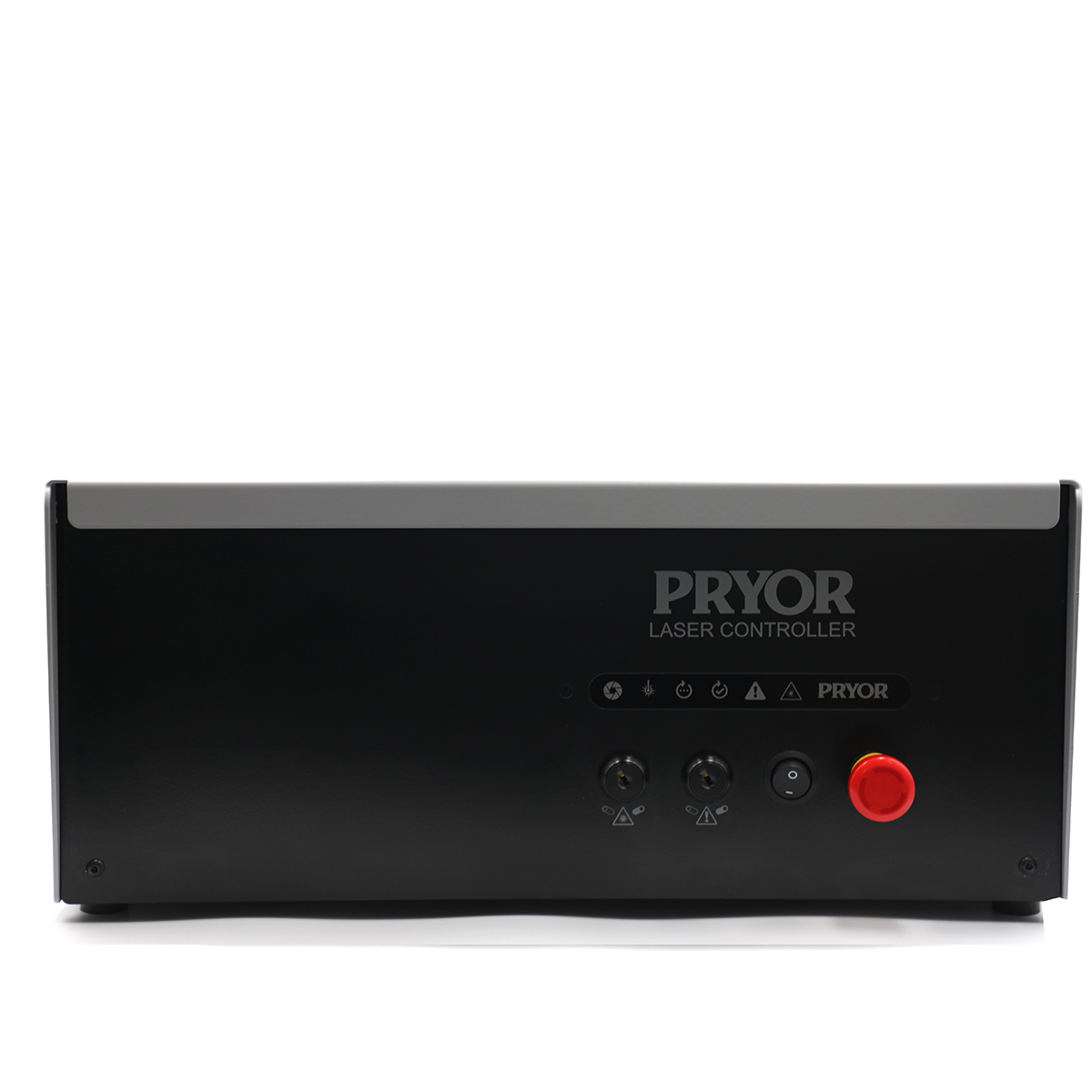
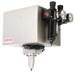
The system is supplied as a Class IV laser system and includes a new marking head paired with a redesigned rack-mount controller. The new integrated laser marking system controller is slimmer and lighter than its predecessor, with a cleaner profile and more flexibility in how it can be fixed and located within a cabinet or rack.
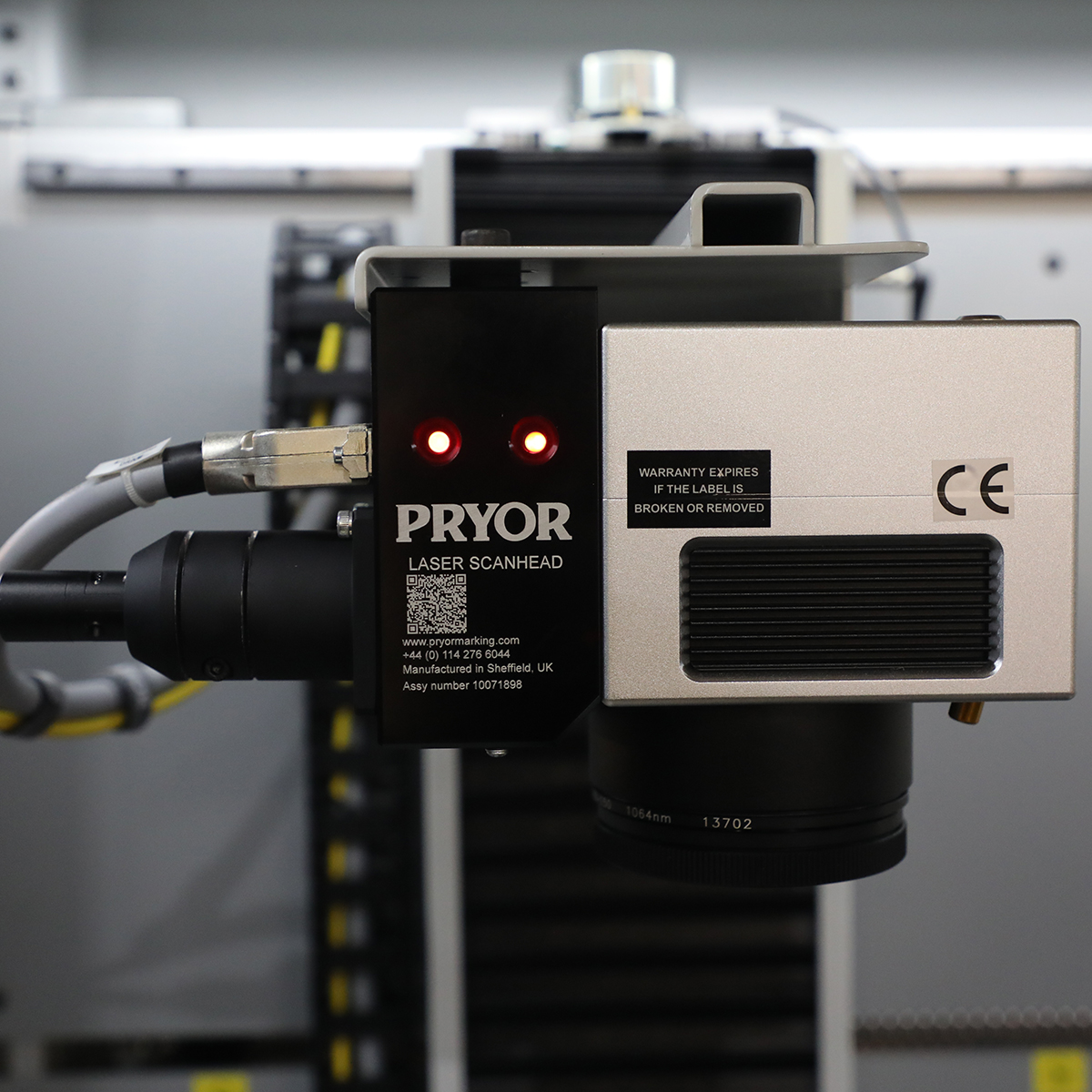
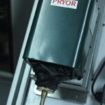
The scan head has been redesigned too. It’s noticeably smaller and lighter than the previous version. This means it easier to mount in confined spaces, position on a robot arm, or integrate into a multi-axis system without adding unnecessary bulk.
For integrators, the most important thing about any laser is how it communicates to the rest of the production line. The Integrator Laser has been designed from scratch with exactly that in mind. A comprehensive set of standard and optional interfaces cover the full range of possible integration scenarios. From simple PLC start/stop inputs to EtherNet/IP, PROFINET, OPC-UA, and TCP/IP socket connections. And whether you’re working with Siemens, Allen-Bradley, or a bespoke software platform, there’s a communication option for you.
As with all lasers, the marking process is non-contact, which removes the need for complex fixturing. It can mark static parts or track components in motion, making it a strong fit for high-speed lines, robot cells, conveyor systems, and rotary tables. It handles metals, plastics, and coated materials with clean and consistent results.
Key Integrator Laser Systems points at a glance:
- MOPA fibre laser source – superior control and broader material capability than conventional pulsed lasers
- Available in 30W, 50W, 100W, and 200W configurations
- New compact, lightweight scan head with smaller profile for easier mounting and positioning.
- Redesigned rack-mount controller that is lighter, more compact, and has a wide range of fixing and mounting options
- Comprehensive communication options: RS-232, Digital I/O, USB, Ethernet TCP/IP, EtherNet/IP, PROFINET, OPC-UA and more
- Suitable for inline and marking-on-the-fly applications.
- Handles metals, plastics, and coated materials with permanent, high-contrast results
- Fully compatible with Pryor’s traceability software.
- Sold as a Class IV laser system
In short, it’s a purpose-built integrator laser solution that slots into automated manufacturing with minimal fuss and plenty of performance headroom. The Pryor laser marking head can be supplied as a stand-alone class 4 laser product together with a rack mount controller for integration to a production line or cell.
Power Options Available
Watt
Watt
Watt
Watt
- Features
- Laser Technical Specification
- What is a MOPA laser source?
Features
Integrators and OEM manufacturers need a laser that fits neatly into a wider architecture, communicates reliably with everything around it, and simple and easy to use. This updated version of our popular integrator laser is a meaningful step forward in every area that matters to our customer. Designed and built for ease of integration, whilst maintaining the Pryor quality and performance.
MOPA Laser Source
The switch from conventional pulsed fibre to MOPA technology is the most significant change in this generation of the Integrator Laser. The key advantage is control. Where a standard pulsed fibre laser fires pulses at a fixed duration, a MOPA source allows pulse width to be set independently of the repetition rate. That gives far greater flexibility in how the mark is produced, meaning cleaner results on heat-sensitive materials, better contrast on aluminium, sharper marks on plastics, and more consistent performance across a wider frequency range. For integrators building systems that handle a variety of components or materials, that additional control can open up lots of new opportunities and potential products for laser marking.
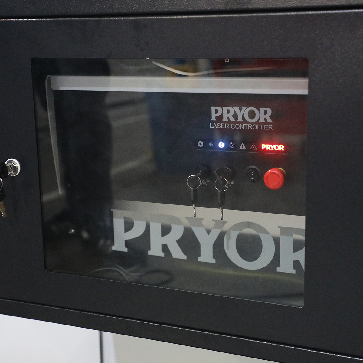
Redesigned Controller
The new controller has been redesigned in terms of aesthetics and practicality. It’s lighter and slimmer than the previous version, with a cleaner look that sits more comfortably in a modern automation cabinet or next to a production line. More importantly, there are more options for how it can be fixed and located, useful when the system needs to integrate within an existing location or where weight is a critical factor.
New Compact Scan Head
The laser scan head is also new. It’s smaller and lighter than the previous version, ideal for when mounting in a restricted space, integrating onto a robot arm, or designing a multi-axis cell with tight constraints. Less bulk makes positioning easier and allows for integration possibilities that would have required more compromise with the previous design.
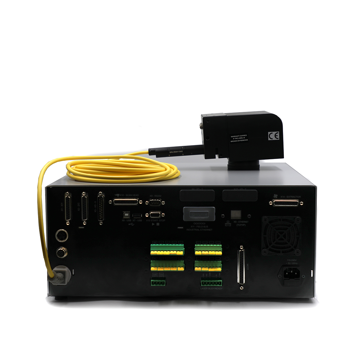
Communication and I/O
The system supports two operating modes: 1) Embedded/standalone and 2) PC-controlled, and the communication options available reflect the full range of scenarios integrators might encounter during a project.
In standalone mode, standard interfaces include:
- RS-232
- 24V digital I/O (8 inputs, 6 outputs, expandable to 24 inputs and 18 outputs across three banks)
- a dedicated start/stop input
- USB for scanner or reader connectivity
For fieldbus environments, optional modules add EtherNet/IP for Rockwell/Allen-Bradley PLC systems or PROFINET for Siemens environments. Ethernet TCP/IP socket connectivity is also available for custom software or MES integration.
In PC controlled mode using Pryor’s traceability software, the system gains OPC-UA connectivity, a vendor-neutral, multi-brand protocol with bidirectional data exchange. That means the wider automation system can send data to the laser and receive confirmation, or variable data, back in real time. This provides live traceability verification without additional software layers.
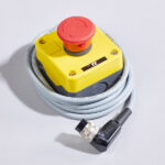
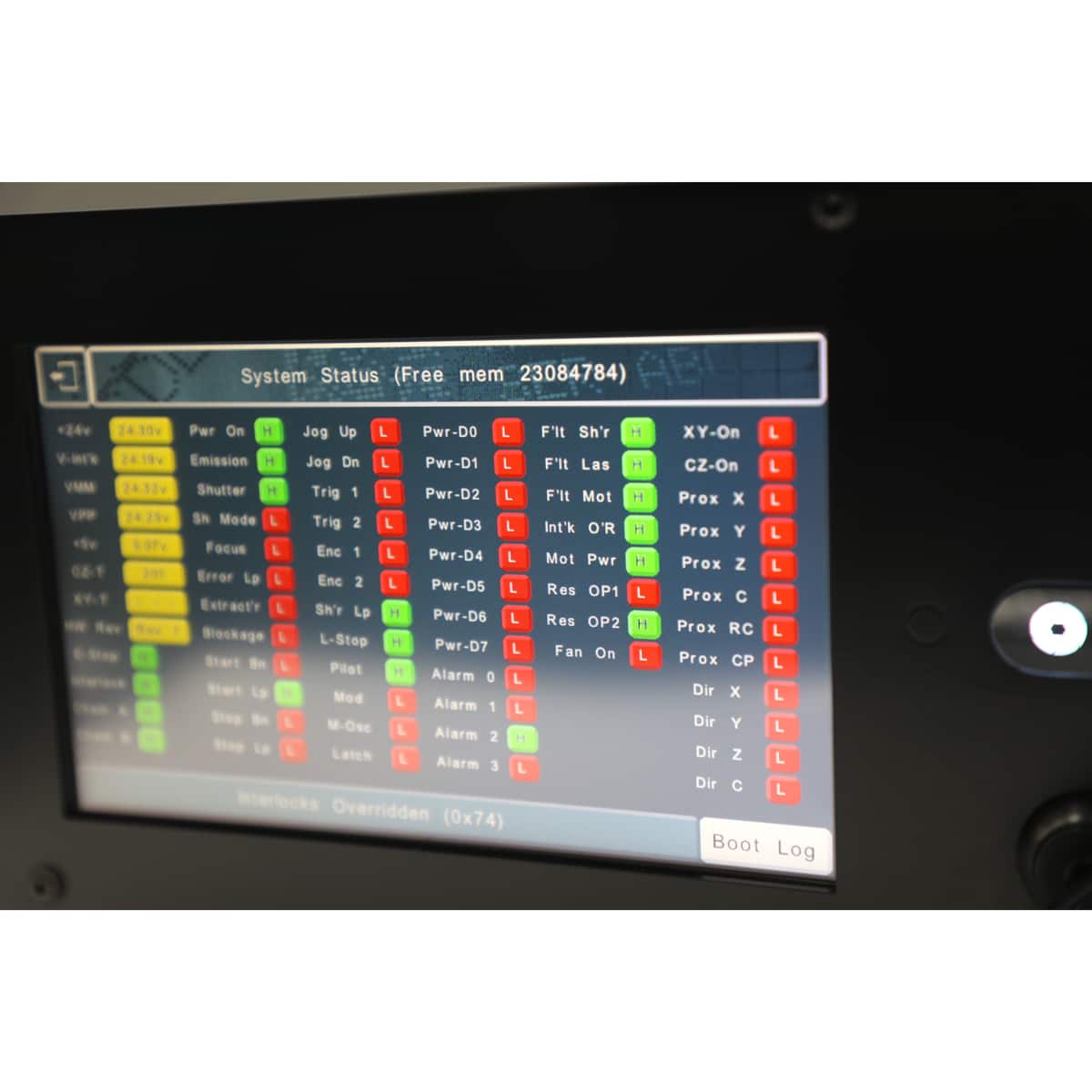
For safety, it has:
- dual-channel door interlocks
- multiple E-Stop inputs
- a Busy/Ready relay output
- E-Stop monitoring contacts for integration into the safety circuit of a wider system
If you need guidance on selecting the right communication options for your project, our technical sales team is happy to advise.
Laser Technical Specification
| 30W MOPA | 50W MOPA | 100W MOPA | 200W MOPA | |
| Nominal Power | 33 ±2 W | 54 ±2 W | 105 ±3 W | 205 ±3 W |
| Mode of Operation | Pulsed & Continuous | |||
| Polarization | Random | |||
| Power Tunability | 10 – 100% | |||
| Wavelength (nm) | 1060 – 1070 | |||
| Single Pulse Energy | ≤1.1 mJ | ≤1.8 mJ | ||
| Repetition Frequency | 1 – 4,000 kHz | 1 – 8,000 kHz | ||
| Pulse Width | 2 – 500 ns | 10 – 500 ns | ||
| Red Guide Laser | 200 – 1000 µW (Class 2) | |||
| Operating Temperature | 0 to 40°C | |||
| Humidity | 10 to 95% | |||
| Cooling Method | Air Cooling | |||
| Bending Radius | Min. 100 mm | |||
Lens Options
| Lens Option | Marking Window Size | 30W | 50W | 100W | 200W |
| F100 Lens | 70×70mm | ✓ | ✓ | – | – |
| F160 Lens (Fused Silica) | 100×100mm | ✓ | ✓ | – | – |
| F163 Lens | 110×110mm | ✓ | ✓ | – | – |
| F210 Lens | 150×150mm | ✓ | ✓ | – | – |
| F330 Lens | 200×200mm | ✓ | ✓ | – | – |
| FT100 Lens | 60×60mm | – | – | ✓ | ✓ |
| SL178 Lens | 70×70mm | – | – | ✓ | ✓ |
| FT150 Lens | 100×100mm | – | – | ✓ | ✓ |
| FT165 Lens (Annealed Marks) | 100×100mm | – | – | ✓ | ✓ |
| FT254 Lens | 150×150mm | – | – | ✓ | ✓ |
| FT330 Lens | 215×215mm | – | – | ✓ | ✓ |
| FT420 Lens | 290×290mm | – | – | ✓ | ✓ |
Communication Options
Communication & I/O Options
The laser controller supports two fundamental operating modes. The interfaces available depend on which mode suits your application.
| Mode 1 — Embedded / Standalone
The laser runs autonomously using its onboard controller and layouts. A touchscreen is recommended. Best suited to applications with a defined, repeatable set of marking layouts. |
Mode 2 — PC-Controlled
The laser is driven by MarkMaster or Traceable-IT software running on a connected PC via USB. The better choice where significant part variety exists and frequent layout creation or modification is required. |
Standard Interfaces
The following ports and connectors are fitted as standard on every unit.
| Name / Interface | Protocol | What It Does | Availability |
| USB Type-A | USB Host | Connect a USB barcode scanner to feed data into embedded layouts. Only certain scanner brands are compatible — confirm compatibility before ordering. | Standard |
| USB Type-B | USB Device | Connects the laser to a PC running MarkMaster or Traceable-IT for full PC control, or for downloading layouts to the embedded system. | Standard |
| RS-232 Serial | RS-232 | Load layouts, insert variable data, and trigger marks when running standalone. Ideal for simple PLCs or legacy automation systems. | Standard |
| Digital I/O | 24 V DC | 8 inputs and 6 outputs (24 V) for connecting sensors, clamps, indicator lamps, feed systems and other automation equipment. Expandable to 24 inputs and 18 outputs via additional I/O modules. | Standard |
| Start / Stop | 24 V DC | Remote start/stop input. Wire directly to a PLC output or connect a physical push-button box to trigger and halt marking cycles. | Standard |
Safety & Interlock Connectors
All safety connections use green pluggable screw-terminal connectors and are dual-channel for compliance with functional safety requirements.
| Connector | Description |
| Laser Busy / Ready Relay | Volt-free relay contact output. Allows an external PLC to monitor whether the laser is marking (Busy) or has completed its cycle (Ready). Essential for sequencing in automated lines. |
| Door Safety Interlocks | 1 × non-overridable dual-channel interlock (IKA/IKB NOR) plus up to 4 × overridable dual-channel interlocks (IKA/B 1–4, key-switch override). Wire to door switches on enclosures or access panels. |
| Emergency Stop Inputs | Up to 4 × dual-channel E-Stop inputs (ESA/B 1–4). Connect external emergency stop buttons to integrate the laser into the safety circuit of a wider system. |
| E-Stop Monitoring Outputs (ESA/B OUT) | Dual-channel volt-free feedback contacts for a PLC to monitor the laser’s entire E-Stop circuit — including the front-panel button. Enables wider system E-Stop chain integration. |
Optional Embedded Communication Modules
These interfaces are available as optional add-ons for embedded/standalone operation. All are used for the same core purpose — loading layouts, inserting variable data, and triggering marks — using different industrial protocols to suit different automation architectures.
| Name / Interface | Protocol | What It Does | Availability |
| Ethernet TCP/IP | TCP/IP Socket | Send commands over a standard network connection. Suited for integration with custom PC-based software or MES systems that can open a TCP/IP socket connection. | Optional |
| EtherNet/IP (Anybus) | EtherNet/IP | Fieldbus module for Rockwell / Allen-Bradley PLC environments. Load layouts, insert variables, and trigger marks directly from your PLC programme. | Optional |
| PROFINET (Anybus) | PROFINET | Fieldbus module for Siemens PLC environments. Load layouts, insert variables, and trigger marks directly from your PLC programme. Note: only one Anybus module can be fitted at a time — specify the required fieldbus protocol at time of order. | Optional |
PC Software Communication Options
When the laser is controlled by Pryor PC software, communication interfaces are handled by the software on the host PC. The laser connects to the PC via USB.
| Interface | Capability | MarkMaster 2.0 / Traceable-IT | MarkMaster 4 |
| USB (PC Port) | Connect barcode scanners, RFID tag readers, or any device that presents as a USB keyboard — data is passed directly into the software as a variable. | ✓ | ✓ |
| RS-232 (PC Serial Port) | Load layouts, insert variable data, and trigger marks from an external device or PLC connected to the PC’s serial port. | ✓ | – |
| Ethernet TCP/IP (PC Network) | Load layouts, insert variables, and trigger marks via TCP/IP socket messages over the PC’s Ethernet or Wi-Fi connection. Integrates with factory MES/WMS systems or custom applications. | ✓ | – |
| OPC-UA (PC Network) | Vendor-neutral, standardised protocol supported by all major PLC brands. Uses the PC’s Ethernet or Wi-Fi connection. Supports bidirectional data exchange — load layouts, insert variables, trigger marks, and read variable data back from the layout in real time. | – | ✓ |
| Database Connectivity | Connect directly to SQL or other databases to pull variable data for marking. | ✓ | – |
Quick Reference
Use the table below to identify the most appropriate interface for your integration scenario.
| Scenario | Recommended Interface |
| Standalone laser, simple PLC control | RS-232 Serial or Start/Stop input |
| Standalone laser, Rockwell / Allen-Bradley PLC | EtherNet/IP Anybus module (optional) |
| Standalone laser, Siemens PLC | PROFINET Anybus module (optional) |
| Standalone laser, custom software integration | Ethernet TCP/IP (optional) |
| PC-controlled, simple external trigger | USB to PC + RS-232 or TCP/IP via MarkMaster 2.0 |
| PC-controlled, modern multi-brand PLC environment | USB to PC + OPC-UA via MarkMaster 4 |
| Connecting sensors, clamps or feed systems | Digital I/O — expandable via additional I/O modules |
| Integrating into a machine safety system | Interlock connectors + E-Stop inputs + Busy/Ready relay |
What is a MOPA laser source?
MOPA laser marking is fast, precise, and non-contact, which makes it an ideal technology to build into high-speed production lines. Because there’s no physical contact with the part, there’s no need for additional clamping or fixturing, keeping the integration design clean and the cycle time short.
The variable pulse control that defines MOPA technology means the same system can handle a wide range of marking styles and materials without switching configurations. High-contrast surface marks, deep engraving, annealing on stainless steel, or marking on plastics. The InLaser handles them all within its standard operational envelope.
Key Points
- MOPA laser source for superior material flexibility and marking control
- Variable pulse width across the full frequency range
- High-contrast, permanent marks on metals, plastics, and coated materials
- Non-contact, no fixturing, no consumables
- Capable of marking static or moving parts
- Low running costs throughout the system’s lifetime
- Full suite of communication interfaces for PLC and software integration
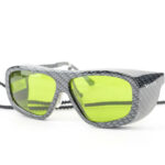
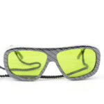
Accessories
-
 Quick View